Analytical Programming
This is my third post about Babbage’s calculating engines. The first two were about the difference engine: why it was important at the time and how it worked. This post is about the analytical engine. The analytical engine is famously the first programmable computing machine, and there was much programming involved both in designing and operating it. In this post I’ll take a look at the various ways you could program the engine and the way programs were used to control the engine internally.
Programming the analytical engine
When the analytical engine is mentioned as the first programmable computer the example you almost always see is one particular program, the one for calculating Bernoulli numbers that was given in note G of Ada Lovelace’s notes on the engine. But that’s only the tip of the iceberg. This post is about the rest of the iceberg. (Don’t worry, I’ll give the Bernoulli program a whole post of its own). The engine could be programmed on roughly three different levels and we’ll take a look at each of them in some detail, but first I’ll give an brief overview of each of them.

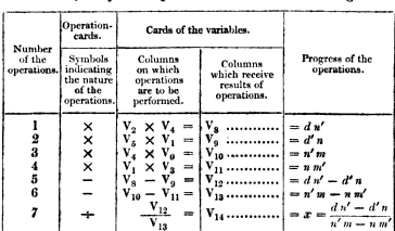
At the highest level programs were written as tables like the one here on the right. That one is taken from Menabrea’s 1842 article about the engine. Each row in the table is an instruction, a mathematical operation to be performed. In modern terms we would call this a register language since all the operation’s inputs and outputs are given explicitly. This is the format that was used in all contemporary articles about the engine and the format of the Bernoulli program. However, a program in table form could obviously not be run by the analytical engine directly, it was more like what we would call pseudocode today. It describes the program you want to execute but it’s not executable itself.
 The way you made executable programs was using punched cards. To run a program written in the table format you would have to translate it into a stack of cards that could be interpreted by the machine. You might think of the cards as a type of bytecode. Babbage seems to have considered this mostly an implementation detail so it’s not super well described, but we still know enough to get a pretty good sense for how card-based programming would have worked.
At the bottom layer there was an internal “microcode” format that controlled how the engine executed each of the punched-card encoded instructions. The microcode programs were encoded as rows of pegs on the side of rotating barrels, like the pins on a music box. The pins controlled operations and data flow within the engine and the control flow of the microprograms themselves. Some of the more complex instructions such as multiplication and division had very elaborate implementations of more than a hundred verticals, Babbage’s name for a single micro-instruction.
In the rest of this post I’ll describe two of these formats, tables and microcode. The punched card format has a separate post which is linked at the end. First though, a quick note on sources. My source for most of this post is some excellent articles by Allan Bromley: The Evolution of Babbage’s Calculating Engines from 1987 and Babbage’s Analytical Engine Plans 28 and 28a – The Programmer’s Interface from 2000. If you want more information these are the articles to read. (Obscenely they are both behind IEEE’s paywall which I suspect is one reason they’re not as widely read as they deserve to be.)
With that let’s get on to the first language level: tables.
Tables
The basic model of the analytical engine is similar to the difference engine but generalized along several dimensions. The difference engine had 8 columns, what we would call registers, with 31 decimal digits of precision (roughly 103 bits). These could be added together in a fixed pattern, right to left. The analytical engine had a much larger number of columns, Babbage considered 1000 to be realistic, and it could add, subtract, multiply, and divide them in any pattern. The columns also had more precision, 50 decimal digits (roughly 166 bits). Each column had an index, i; the i‘th column is written as Vi. The V stands for variable which I’ll use interchangeably with the word column.
The table format for programming the engine, the most high-level format, represents a sequence of instructions as rows in a table. Each row specifies an operation along with the input and output columns. For instance, to calculate (V1 + V2 + V3) and store the result in V4 you would do something like:
| # | op | in | out |
|---|---|---|---|
| 1 | + | V1 + V2 | V4</td> |
| 2 | + | V3 + V4 | V4</td> |
The first instruction adds V1 and V2, storing the result in V4, and the second adds V3 to V4. It’s pretty straightforward really – but in this simple example I’ve cheated and omitted a few details. We’ll be adding those back now.
In modern programming languages we’re used to being able to read a variable as many times as we want with no side-effects. With the analytical engine on the other hand when you read a column what you’re actually doing is transferring the value mechanically from the column to the processing unit, the mill, which causes the column to be cleared. It’s obviously inconvenient if you can’t read a column more than once. To solve this the engine supported two kinds of reads: the simple read where the column is cleared in the process and a the restoring read where the column retains its value. A restoring read works by simultaneously transferring the value to the mill and a temporary storage column and then immediately transferring the value back from temporary storage to the column.
To indicate which kind of read to do there’s an extra field in the table indicating column value changes. If we go back to the program from before, let’s say that we don’t mind that V2 and V3 are cleared but we need to retain V1. We would express that as
| # | op | in | out | vars |
|---|---|---|---|---|
| 1 | + | V1 + V2 | V4 | V1 = V1 V2 = 0 |
| 2 | + | V3 + V4 | V4 | V3 = 0 |
In the first operation we want to restore V1 after it’s been read but let V2 get cleared. In the second instruction we let V3 get cleared and we don’t need to specify what happens when we read V4 because that’s where the result is stored.
This program contains the full information you would need to be able to run it on the engine. The original tables annotate programs some more but anything beyond this is more like comments, it doesn’t change the behavior of the program.

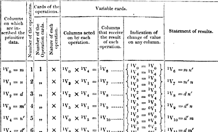
One additional piece of information you’ll see in most of the original programs, the one on the right here is another of Menabrea’s, is that all the column names have a second index in superscript. So where I’ve written V1 one of the original tables would have something like 1V1. The second index indicates how many times the variable has changed. So 1V1 means “the first value stored in V1”, 2V1 means “the second value stored in V1, after it had been overwritten once”. This doesn’t mean that you can recover old values of a variable, it’s just for the programmer to keep track of what the current value is of each variable. You can also write 0V1 which means the original 0 stored in V1 in the case where we haven’t written to that column at all yet. If we add in these indices the program will look like this:
| # | op | in | out | vars |
|---|---|---|---|---|
| 1 | + | 1V1 + 1V2 | 1V4 | 1V1 = 1V1 1V2 = 0V2 |
| 2 | + | 1V3 + 1V4 | 2V4 | 1V3 = 0V3 |
(The 0V2 assignment is just a convention, it means the same as resetting V2 to its initial state where it contained 0).
This is the language used to write the first computer programs. Even though it’s unusual it will look familiar to any modern programmer familiar with assembly programming. There is no way to specify control flow even though there is some indication in the Bernoulli program that it had been considered. These are basically straight-line sequences of mathematical operations on a set of variables. And being pseudocode the conventions weren’t fixed, they were changed and adapted by the authors to fit the programs they were writing.
The microprogram format is at the other end of the spectrum; where the tables were high-level and meant for communicating programs clearly the microprograms where low-level and written and understood only by Babbage, at least until recently.
Microprograms
The analytical engine could perform a number of complex operations including multiplication and division. To give a sense for how complex I’ll give an example of how the engine would multiply two numbers.
Say we instruct the engine to multiply 17932 with 2379. The multiplication logic would first determine which of the operands had the fewest digits and put that in one register. (The computing mill had a number of internal storage columns that were used to hold partial results during individual operations. I’ll call those registers to distinguish them from the user-accessible columns). The other number, the one with most digits would be used to generate a table of all the multiples of that number from 2 to 9, using addition. In this case that’s 17932:
| factor | value |
|---|---|
| 1 | 17932 |
| 2 | 35864 |
| 3 | 53796 |
| 4 | 71728 |
| 5 | 89660 |
| 6 | 107592 |
| 7 | 125524 |
| 8 | 143456 |
| 9 | 161388 |
Once this table had been built the engine would scan through the other number, in this case 2379. For each digit it would look up the corresponding multiple in the table, shift it left by an amount corresponding to the significance of the digit (that’s base 10 shift), and add the resulting values as it went:
| digit | product | running total |
|---|---|---|
| 9 | 161388 | 161388 |
| 70 | 1255240 | 1416628 |
| 300 | 5379600 | 6796228 |
| 2000 | 35864000 | 42660228 |
Adding those four values together you get 42660228, the product of 17932 and 2379, calculated using the primitive operations of addition and multiplication by 10. The whole operation took time proportional to the number of digits of the shortest of the input numbers. Unlike the difference engine which stored numbers as tens complement the analytical engine stored the sign of the number as a separate bit. That way the multiplication could be unsigned and the sign could be computed separately. This meant that the engine had two zeroes, plus and minus.

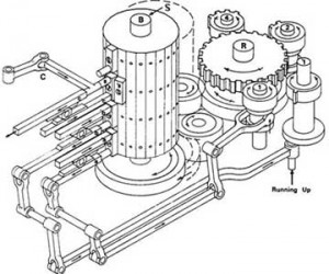
Back to multiplication. The engine needed an internal control mechanism to take it through this complex process and what it used was a microprogram encoded by pegs on a rotating barrel. You can see a simplified diagram of the barrel here on the right. Each “cycle” of the microprogram proceeds in the same way.
First the barrel is pushed left and the pegs along the vertical edge press against a row of levers which causes them to engage or disengage other parts of the engine. Because of the way the pegs are aligned with the vertical edge of the barrel Babbage called a single such instruction a vertical.
Second, the barrel is pushed to the right and connects to the big gear you see to the right of it in the diagram. That gear, and the gears connected with it, Babbage called the reducing apparatus. That’s what controls the flow of the program. The reducing apparatus rotates the barrel some amount in either direction to select the next vertical to apply. At the same time any other components that were engaged by the current vertical perform their operation, for instance a single step of building the multiplication table. The reducing apparatus takes input from those other components so for instance it may move the barrel different amounts depending on whether the last addition overflowed. That’s the arm on the far right (Babbage called overflow “running up”). The reducing apparatus is controlled by the barrel itself so each vertical explicitly specifies how the reducing apparatus should rotate it to the next vertical. You’ll notice that the three gears you see near the reducing apparatus’ main gear have 1, 2, and 4 teeth respectively. By engaging a combination of them one vertical could have the reducing apparatus rotate the barrel any number of steps between 1 to 7. In modern terms, each micro-instruction contains an explicit relative branch, conditional or unconditional, to the next microinstruction. As you can see this is a highly sophisticated and general mechanism. The only disadvantage is that it’s slow – a single cycle takes a few seconds so a multiplication can take several minutes.
As you would expect the diagram above is simplified, in practice there were multiple barrels and they were much larger both in the number of pegs for each vertical and number of verticals per drum. I haven’t been able to find any of Babbage’s actual microprograms unfortunately so for now all I know are the basic principles, and we know that designing them was one of Babbage’s main interests in designing the engine.
The third program format is the punched cards which is what would have been used by an operator of the engine. I’ll look at those in some detail because they give a good sense of what it would have been like to work with the engine in practice. To keep this post to a reasonable length I’ve broken that out into its own post called punched cards.